Microflow 3D is a CFD platform (including preprocesor, solver and prostprocessor interface) for scientific code development for simmulations of processes, that is based on the lattice-Boltzmann method. It is developed at the Wroclaw University of Science and Technology (Poland).
The main goal of our project is to build up a 3D framework for scientific LBM code development for transient flow simulations in comlex geometries with a special attention to microflows in channels of microsystems and bio-chips. Another field of application are flows in narrow blood vessels: capillaries, venules and arterioles in organs and tissues, also in pathologically degenerated tissues like tumors.
The area of application of solver is not limited to small scale flows phenomena. Microflow 3D is capable to resolve complex problems from various branches of applied science e.g. mechanical, chemical and biomedical engineering.
This documentation describes code structure and data structures dependencies and also shortly introduces naming conventions related to physical models that are incorporated to the code.
People who are looking for user's guide are invited to read
tutorials posted on the project's website
www.microflow.pwr.edu.pl
Data flow diagram
Data flow structure and dependencies within the Microflow 3D platform are presented below on the block diagram.
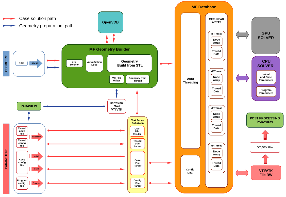
1. Microflow 3D block diagram.
Data flow in the Microflow program takes place in two ways.
The first - short circuit (marked in blue) is used during pre-processing step when the boundary conditions of the solution are defined.
The second - full circuit (marked in red) uses previously fully defined boundary conditions to perform calculations.
In the first case, the geometry of the system from the STL file is read into the B-tree-like structure of OpenVDB, and then voxelized and processed (boundary nodes are automatically detected) using the functions provided by the OpenVDB library. As a result, we get a sparse data structure - a Cartesian volumetric grid, which is saved in a VTI file using the functions provided by the VTK library. This file is then processed in the Paraview to determine the nodes lying on the boundary surfaces - inlet and outlet. The coordinates of the boundary nodes are saved in CSV text files and combined with the parameters defining the boundary conditions in the form of uid-thread objects saved in the thread_params.cfg file. Short data circulation is called by the Microflow -g command. In this case, the calculations are not initialized.
The full data circuit is called after the case parameters have been fully defined. Again, the case geometry is read from the STL file and processed using the OpenVDB library to generate a volumetric grid. Then the configuration files: case_params.cfg, thread_params.cfg, the .csv nodeForAutoThreading files and the Microflow.cfg file are parsed. Geometry boundary nodes, as well as fluid nodes, are classified and assigned automatically to the appropriate MFThrad objects. As a result, an array of MFThrad objects is created. Each MFThrad object stores a dense array of associated nodes and additional parameters common to all associated nodes, including pointers to data processing functions at the stage of pre-collision, collision, and propagation. Each Node object stores two arrays of pre- and post-collision particle distribution, an array of pointers to neighboring nodes (propagation table) and the Node coordinates in rare geometry. MFDatabase data are made available to solvers which provide the definition of functions that process the data of MFThread objects and are responsible for their sequential calling. MFDatabase objects have interfaces that enable automatic saving of calculation results in a VTI file. Calculation results are visualized in the Paraview program.
CPU Solver structure - main function
The main function of MFSolver_CPU.cpp is responsible for the sequential calling of data processing functions.
The structure of the main function is partitioned into 7 consecutive blocks:
Initialization block
Geometry building block
Case and program parameters initialization block
Threads building block
Threads data initialization block
Main loop block
Postprocessing block
Initialization block
This block calls functions that set basic parameters of program and case.
cout << "Microflow framework >>> Initialization info:" << endl;
openvdb::initialize();
CmdLineArgsParser_Ptr->parseCmdLineArgs(argc, argv, pPathToProgramConfigFile, pPathToCaseFolder, pScope, verbose, geometryOnly, CPU_ThreadsNr);
cout << "----------------------------------------------------------------------------------------------------------------------------" << endl;
Geometry building block
A block of instructions responsible for loading from STL file the geometry and processing it to obtain OpenVDB sparse volumetric cartesian grid.
cout << "Microflow framework >>> Geometry building info: " << endl;
Geometry_Ptr->ReadGrid(verbose);
Geometry_Ptr->AutomaticBoundaryFind();
if (geometryOnly) {
Geometry_Ptr->WriteGeometryGridToVtiFile();
Geometry_Ptr->WriteGeometryGridToVDBFile();
cout << endl;
cout << "----------------------------------------------------------------------------------" << endl;
cout << "Geometry file has been generated ***** Goodbye *****" << endl;
cout << "----------------------------------------------------------------------------------" << endl;
exit(0);
}
Geometry_Ptr->FluidAddFromThreadFile();
Geometry_Ptr->SolidAddFromThreadFile();
Geometry_Ptr->BoundaryAddFromThreadFile();
Geometry_Ptr->Clean();
cout << "----------------------------------------------------------------------------------------------------------------------------" << endl;
Case and program parameters initialization block
Two objects are initialized from parser object data: ProgramParameters_Ptr and CaseParameters_Ptr.
cout << "MFSolver_CPU >>> Case and program parameters initialization info: " << endl;
if (CPU_ThreadsNr == 0 && CaseParameters_Ptr->CPU_ThreadsNr == 0)
CPU_ThreadsNr = omp_get_num_procs();
else if (CPU_ThreadsNr == 0 && CaseParameters_Ptr->CPU_ThreadsNr != 0)
CPU_ThreadsNr = CaseParameters_Ptr->CPU_ThreadsNr;
cout << "----------------------------------------------------------------------------------------------------------------------------" << endl;
Threads building block
Automatic grid threading. MFThrad array is build.
cout << "MFDatabase >>> Threads building info: " << endl;
cout << "----------------------------------------------------------------------------------------------------------------------------" << endl;
Threads data initialization block
In this block, the MFthread data are initialized. Boundary and initial conditions are setup and basic simulation parameters are calculated.
Also, the initialization of values of Node particle distribution functions MF::Database::Node::FQ19 is done.
cout << "MFSolver_CPU >>> Threads data initialization info: " << endl;
if(verbose) {
}
cout << "----------------------------------------------------------------------------------------------------------------------------" << endl;
Main loop block
The solver main loop realizes sequential calculations, prints on console solution convergence parameters and writes to the file results of the simulation.
The sequence of the main loop functions calls is 1) Propagation, 2) Pre-collision and 3) Collision.
cout << "MFSolver_CPU >>> Main loop info: " << endl;
unsigned int SimStep = 0;
double V_SimError;
double M_SimError;
std::string DataFileName;
const unsigned int ConsoleWriteStep = CaseParameters_Ptr->ConsoleWriteStep_K_W;
const unsigned int FileWriteStep = CaseParameters_Ptr->VTKWriteStep_VTK_W;
const unsigned int VTKFileMaxNumber = CaseParameters_Ptr->VTKFileMaxNumber_VTK_Max;
for (auto & Thread : *ThreadArray_Ptr->m_ThreadsTable_Ptr) {
if (Thread->m_DoPreCollision && Thread->m_DoCollision) {
Thread->DoPreANDCollision(CPU_ThreadsNr);
}
else if (Thread->m_DoCollision) {
Thread->DoCollisionOnly(CPU_ThreadsNr);
}
else if (Thread->m_DoPreCollision) {
Thread->DoPreCollisionOnly(CPU_ThreadsNr);
}
}
DataFileName = (ConfigData_Ptr->CaseFolder + ConfigData_Ptr->getProgramStringParam("OutputFile") + std::to_string(SimStep));
Geometry_Ptr->m_MFGrid_GeometryGrid_Ptr->saveAllDataToVTIFile(ThreadArray_Ptr, ConfigData_Ptr, DataFileName);
std::cout << std::endl;
std::chrono::time_point<std::chrono::high_resolution_clock> TimeStart = std::chrono::high_resolution_clock::now();
V_SimError = CaseParameters_Ptr->Sc_VelocityResidueError_ErrV + 1;
M_SimError = M_SimError > CaseParameters_Ptr->MassFlowError_ErrM + 1;
while ((V_SimError > CaseParameters_Ptr->Sc_VelocityResidueError_ErrV) || (M_SimError > CaseParameters_Ptr->MassFlowError_ErrM)) {
SimStep++;
for (auto & Thread : *ThreadArray_Ptr->m_ThreadsTable_Ptr)
if (Thread->m_DoPropagation)
Thread->DoPropagation(CPU_ThreadsNr);
if (SimStep % ConsoleWriteStep == 0)
if (FileWriteStep != 0 && SimStep % FileWriteStep == 0){
cout << std::setw(194) << std::setfill('=') << "=" << std::setfill(' ') << std::endl;
if(VTKFileMaxNumber > 0 && SimStep / FileWriteStep > VTKFileMaxNumber) {
std::string ErraseFileName = (ConfigData_Ptr->CaseFolder + ConfigData_Ptr->getProgramStringParam("OutputFile") +
std::to_string(SimStep - VTKFileMaxNumber * FileWriteStep) + ".vti");
cout<<"Errased file: ----> "<<ErraseFileName<<endl;
remove(ErraseFileName.c_str());
}
DataFileName = (ConfigData_Ptr->CaseFolder + ConfigData_Ptr->getProgramStringParam("OutputFile") + std::to_string(SimStep));
Geometry_Ptr->m_MFGrid_GeometryGrid_Ptr->saveAllDataToVTIFile(ThreadArray_Ptr, ConfigData_Ptr, DataFileName);
cout << std::setw(194) << std::setfill('=') << "=" << std::setfill(' ') << std::endl;
}
for (auto &Thread : *ThreadArray_Ptr->m_ThreadsTable_Ptr) {
if (Thread->m_DoPreCollision && Thread->m_DoCollision)
Thread->DoPreANDCollision(CPU_ThreadsNr);
else if (Thread->m_DoCollision)
Thread->DoCollisionOnly(CPU_ThreadsNr);
else if (Thread->m_DoPreCollision)
Thread->DoPreCollisionOnly(CPU_ThreadsNr);
}
}
for (auto & Thread : *ThreadArray_Ptr->m_ThreadsTable_Ptr)
Thread->DoPropagation(CPU_ThreadsNr);
Postprocessing block
The simulation post processing relies mainly on saving the results into a VTI file to allow their easy processing in Paraview.
auto TimeStop = std::chrono::high_resolution_clock::now();
cout << std::setw(194) << std::setfill('=') << "=" << std::setfill(' ') << std::endl;
DataFileName = (ConfigData_Ptr->CaseFolder + ConfigData_Ptr->getProgramStringParam("OutputFile") + std::to_string(SimStep));
Geometry_Ptr->m_MFGrid_GeometryGrid_Ptr->saveAllDataToVTIFile(ThreadArray_Ptr, ConfigData_Ptr, DataFileName);
cout << std::setw(194) << std::setfill('=') << "=" << std::setfill(' ') << std::endl;
 1.8.13